This is a recovered file. The images in this post may be out of order, and there may be duplicates.
Post by vladn » Thu Dec 22, 2011
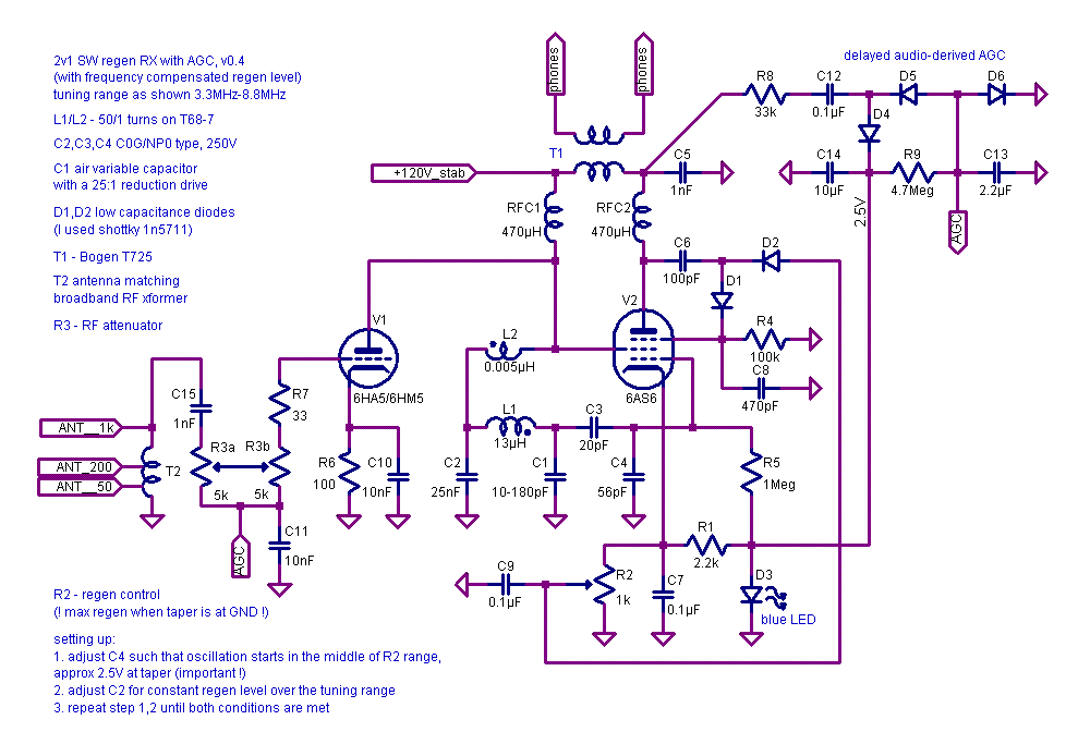
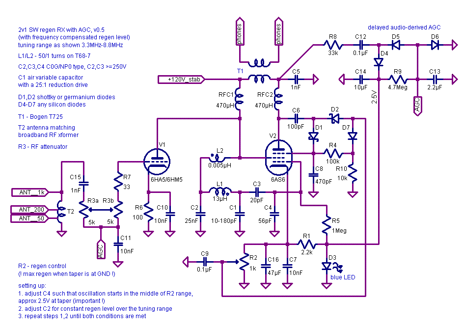
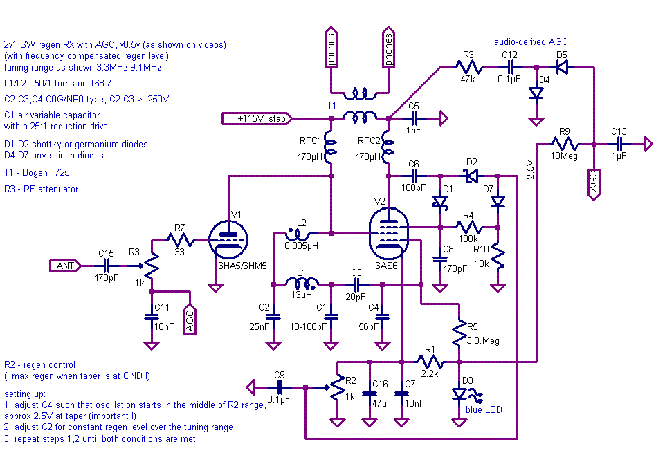
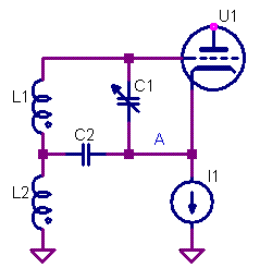
Most wideband regen RXs require substantial adjustment of regen level as you tune across the band. For example most common BCB regens using Armstrong/Hartley/Colpitts topology usually require advancing feedback at the low side of the band. This is the result of frequency dependence of both tank Q-factor and feedback path gain. But there is a solution that allows compensating at least the linear term (tilt) of the regen feedback adjustment dependence on frequency. There are at least 3 class of oscillator feedback network types (I wrote about it earlier) that have substantially different frequency dependence of the feedback gain: class 1: Armstrong, Colpitts, Hartley class 2: Vackar (basic form, fig5 in original Vackar paper [1]) class 3: Clapp/Gouriett Within each class the feedback dependence on frequency is essentially the same (but there could be substantial implementation-specific variations due to tank loading by both active device and antenna). In simulations that I've done a properly equalized loading and tank loss model results in exactly the same feedback frequency dependence within each class. I've tried building a regen based on a different class feedback network (Vackar) and found that it has a frequency feedback dependence tilted in the opposite way for a typical regen: you have to advance regen level as you go higher in frequency. According to my simulations it is tilted even more heavily in the class 3 feedback networks (not tried to build one). However it is possible to constructively combine two feedback types from two oscillator classes in a single detector to eliminate the tilt. I tried it in both simulation and a prototype. By properly adjusting/balancing branch gain I managed to get zero tilt - the lowest and highest frequency points of BCB tuning range required exactly the same regen potentiometer position. The second order term (quadratic) is still uncompensated (you need to reduce regen level somewhat in the middle of the band) but the amount of remaining adjustment is much lower than in conventional class 1 oscillator regen. The receiver that I used for testing combines Armstrong and Vackar feedback types. It is based on a battery-powered dual 1T4 tube regen that I've built with kids some time ago. The board was easy enough to modify so I used it as a testbead. Combination feedback Armstrong/Vackar is particularly easy to do - any standard Armstrong regen can be modified to operate with combined feedback. Below is the circuit diagram of the detector stage. The circuit is a bit unconventional in that it uses screed greed as virtual anode for RF feedback (mostly for legacy reasons as the donor RX was done this way). Here you can see a combination feedback from the screen grid (virtual plate) via L2/L1 coupling (Armstrong) and a current feedback to C2 (Vackar pi-network C2/L1/Ct). Few important notes: 1. Gridleak resistor R1 is connected to ground as the tank has non-zero DC potential. 2. Gridleak capacitor C3 must be rated for B+. 3. R3 is added to damp RFC/C2 resonance 4. I connected antenna to point A via 1nF capacitor but regular inductive coupling can be used as well. 5. Screed grid has low resitance path to ground for AF but not for RF - the tube is used as pentode for AF and triode for RF. General guidelines for feedback branch balancing: C2 should be several times bigger than maximum value of Ct. L2 should have slightly fewer turns than in conventional Armstrong regen (perhaps 80% or so). Once you get the amount of total feedback right (operating in the middle of regen pot adjustment) - tweak C2 to minimize tilt. Decrease it if the regen level pot needs to be advanced more at the bottom frequency vs top frequency of the tuning range. Increase C2 if the opposite is true. It is possible to build a circuit using conventional feedback from the plate of the pentode. Untested but the idea should be clear: Both circuits use Armstrong-Vackar feedback combination however mathematically they behave similarly to the "extended range" Vackar (fig6 in paper [1]). These circuits using Armstrong feedback in one of the feedback paths are a little bit more friendly in terms of implementation and conversion of existing Armstrong regens. Floating inductor (required by Vackar pi feedback) allows a simple circuit implementation with cathode detector. In this case triode gain/current can be controlled from the grid side by a high impedance network (from an optional voltage stabilizer): Even though I derived the idea of dual feedback directly from the Vackar paper quite some time ago there are other sources pointing to this arrangement. In fact recently I found some old russian RF technician textbook that shows VFO with Armstron-Vackar combination feedback used to stabilize VFO amplitude across the tuning range ([2] in russian, fig4-10, pg79), so in a way I was reinventing a long forgotten wheel here. Nevertheless this concept somehow did not get into regen builders view AFAIK. But I think it is worth exploring for both pure regens and regenerodynes or any tunable regenerative circuit. References: [1] http://n1ekv.org/Oscillators/Vackar_wholepaper.pdf [2] В.К. Лабутин, "Книга Радиомастера", издание 1955г (in russian, I have a .djvu copy, I can post the reference page if requested)


